Managing the integrity of North America’s aging pipeline systems is one of the most challenging undertakings facing today’s engineers employed by pipeline operators. The challenge is further intensified when considering the critical role that pipelines play in the everyday lives of those in North America. Along with advanced inspection and engineering assessment methods, full- scale testing can play an important role in helping pipeline executives and integrity engineers make the best decisions concerning injurious defects. Essentially, full-scale testing helps “sharpen the pencil” to ensure that integrity dollars are spent where they achieve the highest return on investment.
Acuren’s Magnolia Office includes a 14,000 ft2 test facility where failure analysis, mechanical testing, and full-scale destructive tests are conducted. Provided in this article are examples where full-scale testing has been used to evaluate the effects of dents, girth welds, wrinkle bends, and cracks on pipeline serviceability. A discussion is also included on the creation of simulated defects and techniques employed for their creation.
Simulated Defect Creation
Because there are a limited number of real-world features available for experimental assessment, testing often requires the creation of simulated features and defects. An important advantage in creating features is the ability to construct a well-defined test matrix that includes variations of key variables, including corrosion depth and length, dent depth, and crack depth and length.
Corrosion features can be fabricated using conventional machining techniques, electric discharge machining (EDM), and chemical etching to generate a pitted profile. Dents are fabricated by pressing an indenter into the pipe to a prescribed depth, often with internal pressure in the pipe. There are several techniques for fabricating axial cracks, although one of the most repeatable involves the installation of an EDM notch into the pipe wall followed by limited pressure cycling to generate cracking at the base of the notch. Girth weld defects have been created by grinding out a portion of the root pass during weld fabrication or in the case of an existing girth weld, using an EDM notch to generate lack of penetration or incomplete penetration features.
The sections that follow provide examples of how real world and simulated defects were tested destructively to quantify their severity.
Dents
Most pipelines have dents. Since the inception of the pipeline industry, dents have been a threat. Over the past 40 years a significant body of research has been conducted to quantify the threats posed by dents and mechanical damage, including full-scale burst and pressure cycling. Provided in Figure 1 is a photograph showing a dent installation rig and a process by which dents are created in the test lab using an indenter and a hydraulic cylinder. Once the dent us installed in the pipe sample, cyclic pressure is applied to the pipe sample to simulate future operation until a fatigue failure occurs. Figure 2 shows a photo of a dented test sample along with a fatigue crack that developed in the shoulder of the dent after approximately 10,000 pressure cycles were applied.
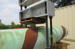
Figure 1: Photograph of a dent installation test rig
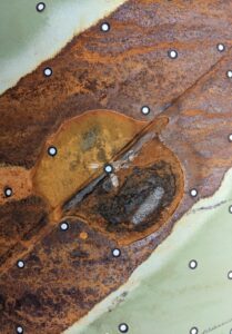
Figure 2: Photograph showing failure of pressure cycled dent
Girth Welds
Pipeline loss of containment from geohazard loading can occur when high axial strains are generated in a displaced pipeline. When the loading is in tension, failure generally occurs as a rupture at a girth weld. When the loading is in compression, a buckle first forms, followed in some instances by a crack at the buckle. Full-scale testing is an ideal means for evaluating the strain capacity of vintage welds and can include lack of penetration features. In full-scale testing, loading includes either axial tension loading as shown in Figure 3, or with the application of bending using a 4-point bending frame as shown in Figure 4. Loading can either be quasi-static or cyclic and conducted with internal pressure in the pipe.
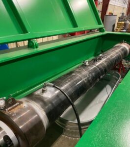
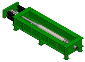
Figure 3: Photograph and schematic of Acuren’s 1-million lbs. tension load frame
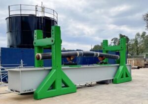
Figure 4: 4-point bending frame
Wrinkle Bends
Wrinkle bends were a common method for constructing bends in transmission pipelines until the mid-1950s. There are literally tens of thousands of wrinkle bends in North America. Wrinkle bends typically fail as circumferentially oriented cracks due to high strain / low cycle bending fatigue. There are several challenges associated with testing wrinkle bends: the first is obtaining actual wrinkles removed from service and the second is simulating the extreme bending loads to which they are subjected.
Provided in Figure 5 is a photograph of Acuren’s high strain-low cycle fatigue frame with a bending capacity of 800,000 ft-lbs. Testing wrinkle bends is an effective method for quantifying the number of cycles a wrinkle feature can survive before leaking. Once this value is determined pipeline operators can determine if geohazard loading in a particular region might generate similar conditions.
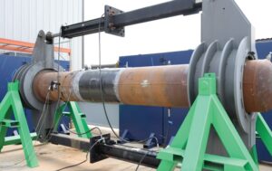
Figure 5: High Strain Bending Frame (800,000 ft-lb Capacity)
Planar Defects and Crack-like Defects
Some of the most significant work involving full-scale testing has been completed in relation to evaluating the impact of planar defects and crack-like features on the pressure capacity of vintage pipe materials. Current crack assessment methods tend to underestimate the failure pressure of vintage pipeline materials having cracks, resulting in excessive excavation and repair. There are several reasons for this, but the primary being the underestimation of fracture toughness using conventional sub-scale testing methods.
There are several approaches for testing cracks in pipe samples. One involves testing cracks in pipe materials removed from service. The other option, and the one more often used in full-scale testing, involves the creation of cracks generated by pressure cycling notches installed via EDM. Figure 5 includes a photograph of an EDM machine used to install notches. Figure 6 includes a macrograph showing a crack that initiated from an EDM notch. Testing involves either pressure cycling the samples until a through-wall crack develops or pressurizing the pipe sample until a burst failure occurs, as shown in Figure 7.
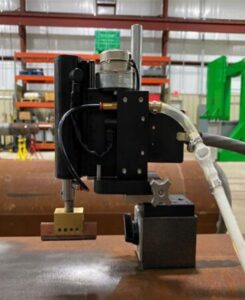
Figure 6: Machine used to install EDM notch
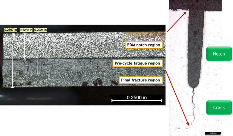
Figure 7: Microcracking observed at the base of an EDM notch
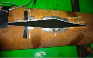
Figure 8: Photograph showing burst test of sample having a crack-like defect
Closing Remarks
The pipeline industry has used full-scale testing since its inception. Even before numerical models and analytic solutions were developed, design and metallurgical engineers learned that pipe materials have limits and the best way to determine those limits involved pressurization to failure. Full-scale testing has and will continue to contribute significantly to our understanding on the capabilities and limitations of pipe materials, repair systems, and other pipeline-focused technologies. A well-designed, instrumented, and executed full-scale test can provide valuable insights for design and integrity engineers charged with the responsibility of constructing and maintaining safe pipelines.